Constant Curvature Kinematics Framework
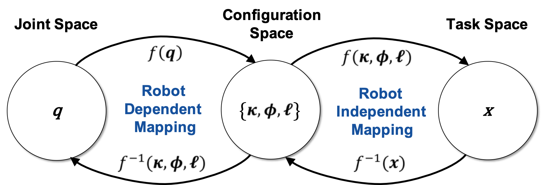
Today, we dive deeper into the common constant curvature kinematics framework. We look at the mappings between joint and configuration space, i.e. the robot dependent mapping, and between configuration and task space, i.e. the robot independent mapping.
Robot Dependent Mapping
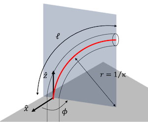 The robot dependent mapping relates the robot’s joint space
\(q \in \mathbb{R}^{n}\) (\(n\) is the number of “joints” or actuators) to
configuration space in terms of circular arc parameters. Arc parameters
define the robot’s configuration and consist of triplets of curvature
\(\kappa \in \mathbb{R}^{m}\), the angle of the plane containing the arc
\(\phi \in \mathbb{R}^{m}\), and arc length \(\ell \in \mathbb{R}^{m}\),
where \(m\) is the number of constant curvature arcs. Alternatively, the
relationship \(\theta = \kappa s\) allows parameterization based on the
angle \(\theta\) by which the arc bends.
The mapping from the joint space of a continuum robot to its configuration space is specific to the robot, as the actuators and unique robot design influence arc parameters in different ways. In particular, consideration of the forces and moments applied by actuators coupled with suitable approximations yields this mapping from actuator variables (pressure, length changes, tension, rotation angles etc.) to curved links described by arc parameters. We will look at different continuum robots and their robot depenbdent mappingin future posts. For now, we will assume that the robot dependent mapping, i.e., from joint to configuration space is known.
Robot Independent Mapping
The robot independent mapping relates the configuration space of a continuum robot, i.e. \(m\) triplets of arc parameters \(\{\kappa,\phi,\ell\}\), to its task space. As with rigid-link serial robots, we may not only be interested in calculating the end-effector position and orientation, but also the pose of all its “joints”. In continuum robot kinematics, the joint pose in task space relates to the position and orientation of the end of each constant curvature arc. Ultimately, we are also interested in knowing the shape of the continuum robot. The shape can be described by a curve in task space.
The geometric features of a space curve or curve in three-dimensional space are a classic topic of differential geometry. In general, each point on a curve \(g\) can be described by a moving frame with respect to some reference frame, for instance the robot’s base. The moving frame has one axis aligned with the tangent of the curve. The other axes of the moving frame must be normal to the curve, but are otherwise allowed to rotate freely about the curve. The curve is parameterized by arc length s.
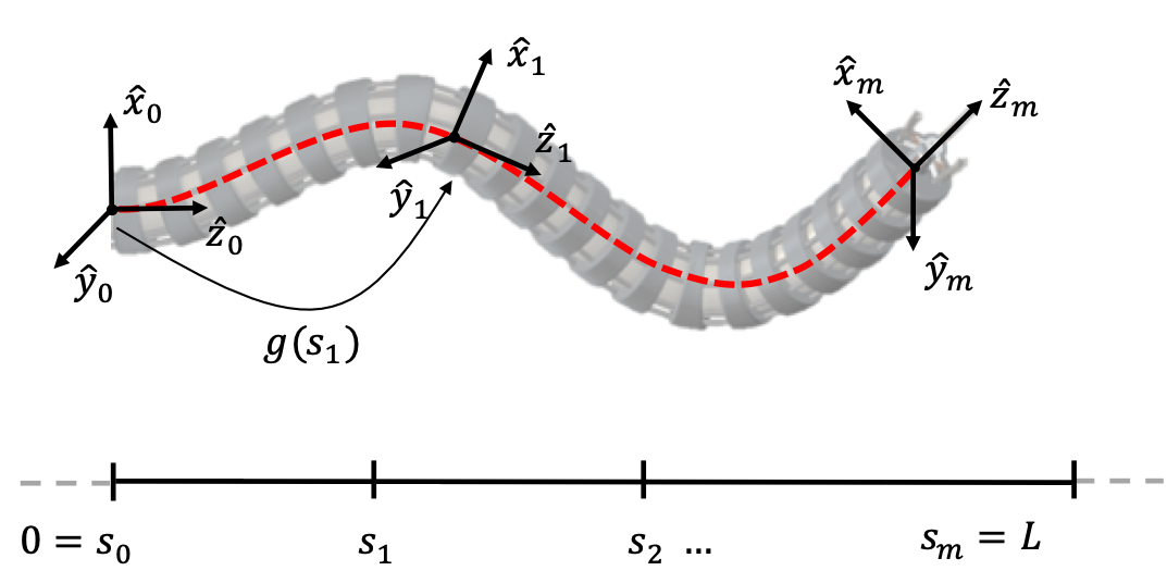
A common assignment of the base frame \(\{ 0\}\) of a continuum robot in its zero configuration is:
- origin at the base
- \(+ {\widehat{\mathbf{z}}}_{0}\) tangent pointing towards the tip of the robot
- \(+ {\widehat{\mathbf{y}}}_{0}\) such that if \(\phi = 0\), positive curvature produces bending about the \(+ {\widehat{\mathbf{y}}}_{0}\)
- orthogonal coordinate frame \({\widehat{\mathbf{x}}}_{0} = {\widehat{\mathbf{z}}}_{0} \times {\widehat{\mathbf{y}}}_{0}\)
The homogeneous transformation along a constant-curvature robot backbone has been derived from a variety of perspectives, such as the geometry of circular arcs, Frenet–Serret frames, and parallel transport frames, all of which lead to equivalent results.
Geometry of Circular Arcs
The geometry of a continuum robot provides a means of determining the pose of points along it using the arc geometry. When \(\phi = 0\), the coordinates of any point on the circular arc of radius \(r\) in the \(\widehat{x}\widehat{z}\)-plane centered at \(\lbrack r\;0\;0\rbrack^{T}\) are \(\mathbf{p}(s) = \lbrack r(1 - \cos\theta)\; 0 \; r\sin\theta \rbrack^{T}\) with \(r = \kappa^{-1}\), \(s \in \lbrack 0,\ell\rbrack\) and \(\theta = \kappa s\). The local frame at \(\mathbf{p}(s)\) is determined as a rotation about the positive y-axis by \(\theta\).
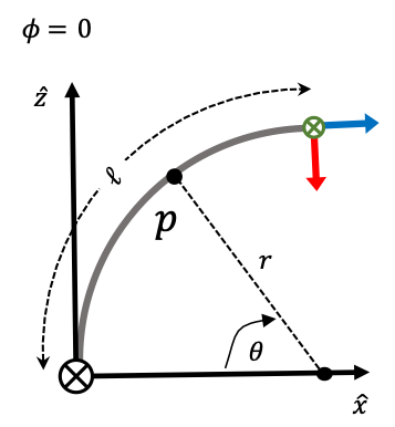 |
| For \(\phi = 0\), the arc lies within the \(\widehat{x}\widehat{z}\)-plane. Here, the local frame at $s+\ell$ is depicted and a point $p$ on the curve. |
When \(\phi \neq 0\), i.e., the arc is rotated about \(\widehat{z}\) by \(\phi\), the homogeneous transformation from the base to a local point \(\mathbf{p}\) at arc length \(s\) can be described as
\[T(s) = \begin{bmatrix} \text{Rot}(\widehat{z},\phi) & \mathbf{0} \\ 0\;0\;0 & 1 \\ \end{bmatrix}\begin{bmatrix} \text{Rot}(\widehat{y},\theta) & \mathbf{p}(s) \\ 0\;0\;0 & 1 \\ \end{bmatrix}\begin{bmatrix} \text{Rot}(\widehat{z},-\phi) & \mathbf{0} \\ 0\;0\;0 & 1 \\ \end{bmatrix}\]Note, the special case of \(\kappa = 0\), i.e., the segment of the robot is straight. In this case, the definition of \(\mathbf{p}(s)\) as stated above does not hold. Instead, it becomes \(\mathbf{p}(\mathbf{s}) = \lbrack 0\;0\;s\rbrack^{T}\).
Frenet-Serret Frames
The fundamental theorem of space curves tells that given the curvature \(\kappa\) and torsion \(\tau\) of an arc-length parameterized space curve, we can recover the curve itself.
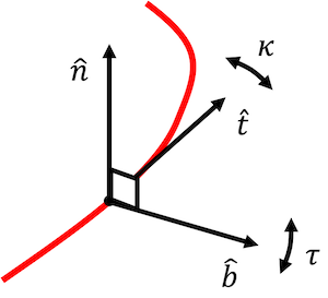 Frenet-Serret frames are defined according to this theorem: One axis is
tangent to the curve, such that we can look at the change in tangent
direction \(\widehat{t}\) as we move along the curve. Since \(\widehat{t}\)
can change at any rate (or not at all), we have another axis of the
frame \(\widehat{n}\) which is the principal normal that expresses the
direction of change, and the scalar \(\kappa\) (the curvature) that
expresses the magnitude of change. By convention we choose \(\widehat{n}\)
to be the normal pointing to the left of the curve, i.e., if at any
point we consider a plane spanned by the tangent and the normal,
\(\widehat{n}\) is a quarter turn in the counter-clockwise direction from
\(\widehat{t}\). Together with a third vector
\(\widehat{b} = \widehat{t} \times \widehat{n}\) called the binormal,
we end up with an orthonormal coordinate frame called the Frenet frame.
\(\tau\) is the torsion, which describes the way the normal and binormal
twist around the curve.
Consequently, how the frame changes as we move along the curve is given by the Frenet-Serret formula:
\(\frac{d}{ds}\begin{bmatrix} \widehat{\mathbf{t}} \\ \widehat{\mathbf{n}} \\ \widehat{\mathbf{b}} \\ \end{bmatrix} = \begin{bmatrix} 0 & \kappa & 0 \\ -\kappa & 0 & \tau \\ 0 & -\tau & 0 \\ \end{bmatrix}\begin{bmatrix} \widehat{\mathbf{t}} \\ \widehat{\mathbf{n}} \\ \widehat{\mathbf{b}} \\ \end{bmatrix}\).
According to the base frame assignment described above, we choose the initial tangent vector \(\widehat{\mathbf{t}}(0) = {\widehat{\mathbf{z}}}_{0}\). The initial normal vector perpendicular to \(\widehat{\mathbf{t}}(0)\) depends on the direction of curvature defined by \(\phi\), so that \(\widehat{\mathbf{n}}(0) = \lbrack\cos\phi\sin\phi 0\rbrack\). Given the parameter \(\kappa\) and \(\tau\), we can recover the curve’s shape. Intuitively this means, that we start drawing a curve, and bend and twist at the prescribed rate. Formally, we can integrate the Frenet-Serret equations, which tell us what is the rate of change of the tangent, normal, and binormal in terms of the curvature and the torsion functions. This is a coupled system of ordinary differential equations. We can solve that for the tangent, binormal and normal. Once we have the tangent, we can integrate it to obtain the curve
\[\mathbf{p}(s) = \int_{0}^{\ell}\widehat{\mathbf{t}}(s)ds\]and obtain the homogenous transformation matrix as
\[T(s) = \begin{bmatrix} \lbrack\begin{matrix} \widehat{\mathbf{n}} & \widehat{\mathbf{b}} & \widehat{\mathbf{t}} \\ \end{matrix}\rbrack & \mathbf{p}(s) \\ 0\;0\;0 & 1 \\ \end{bmatrix}\]which is equivalent to \(T(s)\) derived in the previous section if \(\tau = 0\).
Note, that the Frenet-Serret formula fails for \(\kappa = 0\), i.e. straight lines. Special care must be taken if a segment of a continuum robot could be straight (e.g. in its zero configuration).
Parallel Transport Frames
The parallel transport frame (also referred to as Bishop frame) is an alternative approach to defining a moving frame that is well defined even when the curvature is zero, i.e., the curve has a vanishing second derivative. One can express parallel transport of an orthonormal frame along a curve simply by parallel transporting each component of the frame. The tangent vector and any convenient arbitrary basis for the remainder of the frame are used.
\[\frac{d}{ds}\begin{bmatrix} \widehat{t} \\ \widehat{m_{1}} \\ \widehat{m_{2}} \\ \end{bmatrix} = \begin{bmatrix} 0 & k_{1} & k_{2} \\ - k_{1} & 0 & 0 \\ - k_{2} & 0 & 0 \\ \end{bmatrix}\begin{bmatrix} \widehat{t} \\ \widehat{m_{1}} \\ \widehat{m_{2}} \\ \end{bmatrix}\]with \(\kappa = \sqrt{k_{1}^{2} + k_{2}^{2}}\).
While Frenet-Seret frames are uniquely defined for any regular curve with nonzero curvature, by contrast, a parallel transport frame is not unique but well defined at points where the curvature vanishes. The freedom lies in choosing the initial frame. For instance, we can choose the initial tangent vector \(\widehat{\mathbf{t}}(0) = {\widehat{\mathbf{z}}}_{0}\). The initial vector \({\widehat{\mathbf{m}}}_{1}\) perpendicular to \(\widehat{\mathbf{t}}(0)\) depends on the direction of curvature defined by \(\phi\), so that \({\widehat{\mathbf{m}}}_{1}(0) = \lbrack\cos\phi\;\sin\phi\; 0\rbrack\). We can then solve this coupled system of ordinary differential equations for \(\widehat{\mathbf{t}},{\widehat{\mathbf{m}}}_{1},\text{and}{\widehat{\mathbf{m}}}_{2}\) and integrate the tangent to obtain the curve.
Concatenation of Arcs
Under the constant curvature framework, the shape of a continuum robot becomes a concatenation of constant curvature arcs.
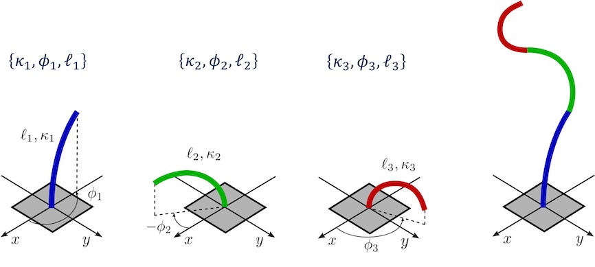
Above, we saw how we can obtain the moving frame along a single constant curvature arc. As the robot dependent mapping usually results in \(m\) triplets of arc parameters \(\{\kappa,\phi,\ell\}\), we have to consider that the succeeding arc is defined with respect to the previous arc’s end frame. Consequently, \(T_{m - 1}(\ell_{m - 1})\) has to be pre-multiplied to the local frame of arc \(m\): \(T_{m}(s) = T_{m - 1}(\ell_{m - 1})T(s)\).
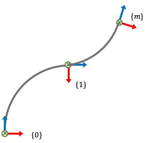
Note, that there may be cases, where the local frame is required to span the cross section of the robot and to express the material orientation.
Further Reading: Webster & Jones1 published a beginner-friendly review on modeling continuum robots using the constant curvature framework. In addition to the different approaches to the robot independent mapping outlined here, they also discuss Denavit-Hartenberg parameters, integral representations, and exponential coordinates. All these methods fundamentally produce the same result for piece- wise constant-curvature robots.
References
-
Webster, R.J. & Jones, B.A., 2010. Design and Kinematic Modeling of Constant Curvature Continuum Robots: A Review. The International Journal of Robotics Research, 29(13), pp. 1661–1683. doi: 10.1177/0278364910368147 ↩
